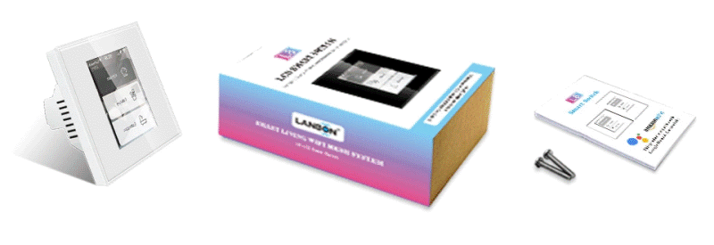
Lanbon L8~

Models~
- L8-HS: 3 Relays - load up to 200W/gang
- L8-HD: 1 Dimmer - load up to 200W/gang
- L8-HB: Boiler switch - load up to 16A
- L8-HT: Thermostat switch - not tested!
Warning
Choose a model that works with Apple HomeKit because those are WiFi versions with the internal antenna connected to the ESP32.
Do NOT buy a version that is powered by Tuya Smart Life because the internal antenna is connected to the Tuya chip. Those devices will have very bad WiFi reception of the ESP32!
Form factor~
- EU model: 86mm x 86mm
- US model: 120mm x 74mm
All models are rated at AC 100-250V ~50-60Hz, the form factor can be a design choice regardless of the continental area.

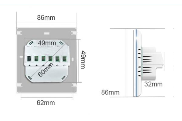
The models have the same recessed housing sliding into the wall, sized 50x50mm, with rounded corners creating a diameter of about 59mm. This makes them suitable for both EU and US wall fixtures. The EU model fits in a properly deployed, standard 60mm round wall box and can be fixed with two side screws (use the screws which belong to the box instead of the ones shipped with the device), the US model fits in the standard rectangular box and can be fixed through the oval holes located 3 1/4" apart. The depth of the wall box has to be at least 35-40mm because some room is needed for the wires coming out straight of the device.
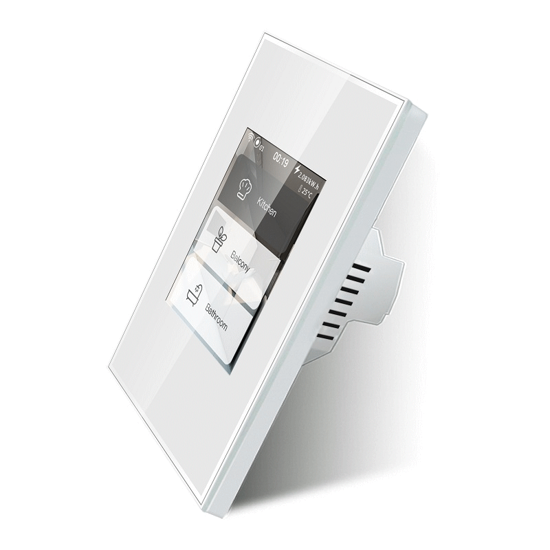
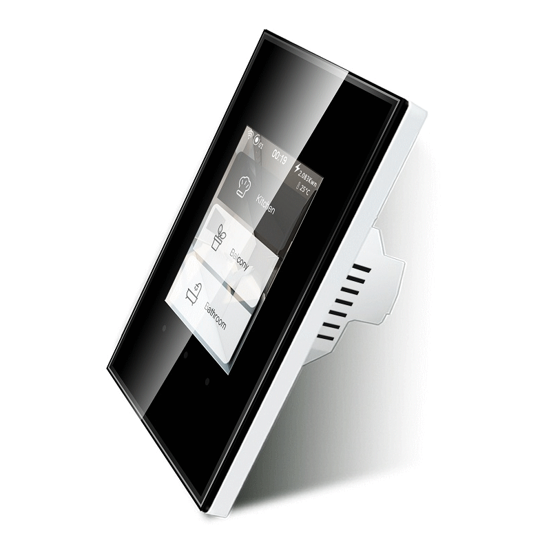
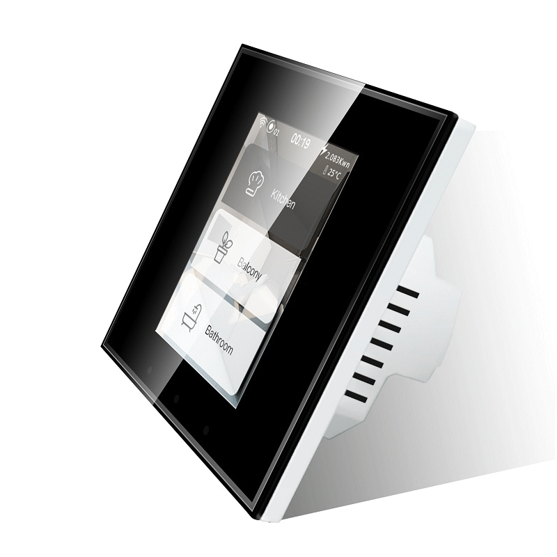
Bezel Color~
- Black
- White
Features:~
- Input voltage 110-250V ~ 50-60Hz AC
- ESP32-WROVER-B
- Capacitive touch screen
- Energy counter
| Pros | Cons |
|---|---|
| 8 MB flash | Mood LEDS not uniform |
| 8 MB PSram | |
| Capactitive touch | |
| Built-in PSU | |
| Energy monitor | |
| Standard wallmount form factor both EU and US |
Note 1
An earlier revision V1.14 (20191203) of the PCB had an analog temperature sensor onboard. It was removed from V1.15 (20200521) of the PCB. You are likely not to get it when buying a recent switch.
Note 2
There is a new V1.17 of the PCB with Tuya support. openHASP does not support the proprietary Tuya chip, but you can still flash the firmware and use the other Lanbon L8 features just fine.
Contents~
Flashing~
Disclaimer
Never connect high-voltage when the panel is not properly secured in place.
You can follow this flashing guide on blakadder.com or this discussion post with instructions and photos to flash the firmware without having to open the device.
Steps:
- Disengage the high-voltage power
- Detach the panel from the PSU power supply
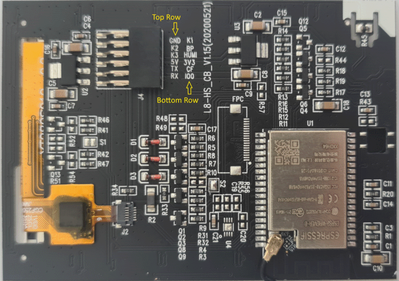
- Connect
RX,TX,IO0,GNDand5Vpins to the female pinheader - Because there is no
RESETpin, you need to powercycle the board whileIO0is connected toGNDto activate flash mode
Make sure you have a USB to serial adapter than can provide sufficient power on the 5V pin. Once the serial connections are made, flash the Lanbon-L8 ESP32 binary like on any other device.
GPIO Settings~
3-gang version L8-HS~
| Pin | Mode | L8-HS | Group | Default |
|---|---|---|---|---|
| 12 | Output | Relay (K3) | 1 | Low (Normal) |
| 14 | Output | Relay | 2 | Low (Normal) |
| 26 | Output | Mood Red | 4 | Low (Normal) |
| 27 | Output | Relay | 3 | Low (Normal) |
| 32 | Output | Mood Green | 5 | Low (Normal) |
| 33 | Output | Mood Blue | 6 | Low (Normal) |
Tip
To configure the GPIOs as light switches at once for L8-HS send to topic hasp/<nodename>/config/gpio a message with payload:
1 | |
1 | |
Example jsonl
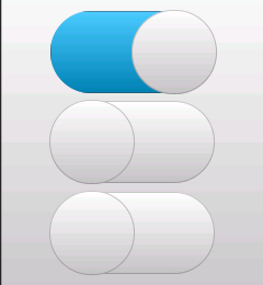
To create a page displaying the local relays as switches, try this very simple pages.jsonl:
1 2 3 | |
Dimmer version L8-HD~
| Pin | Mode | L8-HD | Group | Default |
|---|---|---|---|---|
| 12 | Output | Dimmer TX (K3) | 1 | Low (Normal) |
| 26 | Output | Mood Red | 4 | Low (Normal) |
| 32 | Output | Mood Green | 5 | Low (Normal) |
| 33 | Output | Mood Blue | 6 | Low (Normal) |
Warning
There are two versions of the dimmer configuration: EU and AU. The protocol used to command the dimmer module differs between the two!
Make sure that you have the correct type configured under your GPIO Output settings for pin 12. Use the AU configuration for any 120V/US compatible dimmer modules.
Tip
To configure the GPIOs at once for L8-HD send to topic hasp/<nodename>/config/gpio a message with payload:
EU version:
1 | |
AU/US version:
1 | |
Boiler version L8-HB~
| Pin | Mode | L8-HB | Group | Default |
|---|---|---|---|---|
| 26 | Output | Mood Red | 4 | Low (Normal) |
| 27 | Output | Relay 16A (K1) | 1 | Low (Normal) |
| 32 | Output | Mood Green | 5 | Low (Normal) |
| 33 | Output | Mood Blue | 6 | Low (Normal) |
Tip
To configure the GPIOs at once for L8-HB send to topic hasp/<nodename>/config a message with payload:
1 | |
Developer Note
You can build your own firmware with GPIOs and many other parameters pre-configured in user_config_override.h as factory defaults for Lanbon L8.
Wiring Diagrams~
The switch supports several wiring configurations:
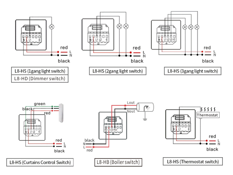
Warning
Always follow the instructions from the installation guide and local safety regulations. Consult a licensed electrician when changing your electrical wiring.
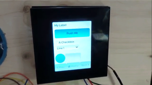
Product Video~
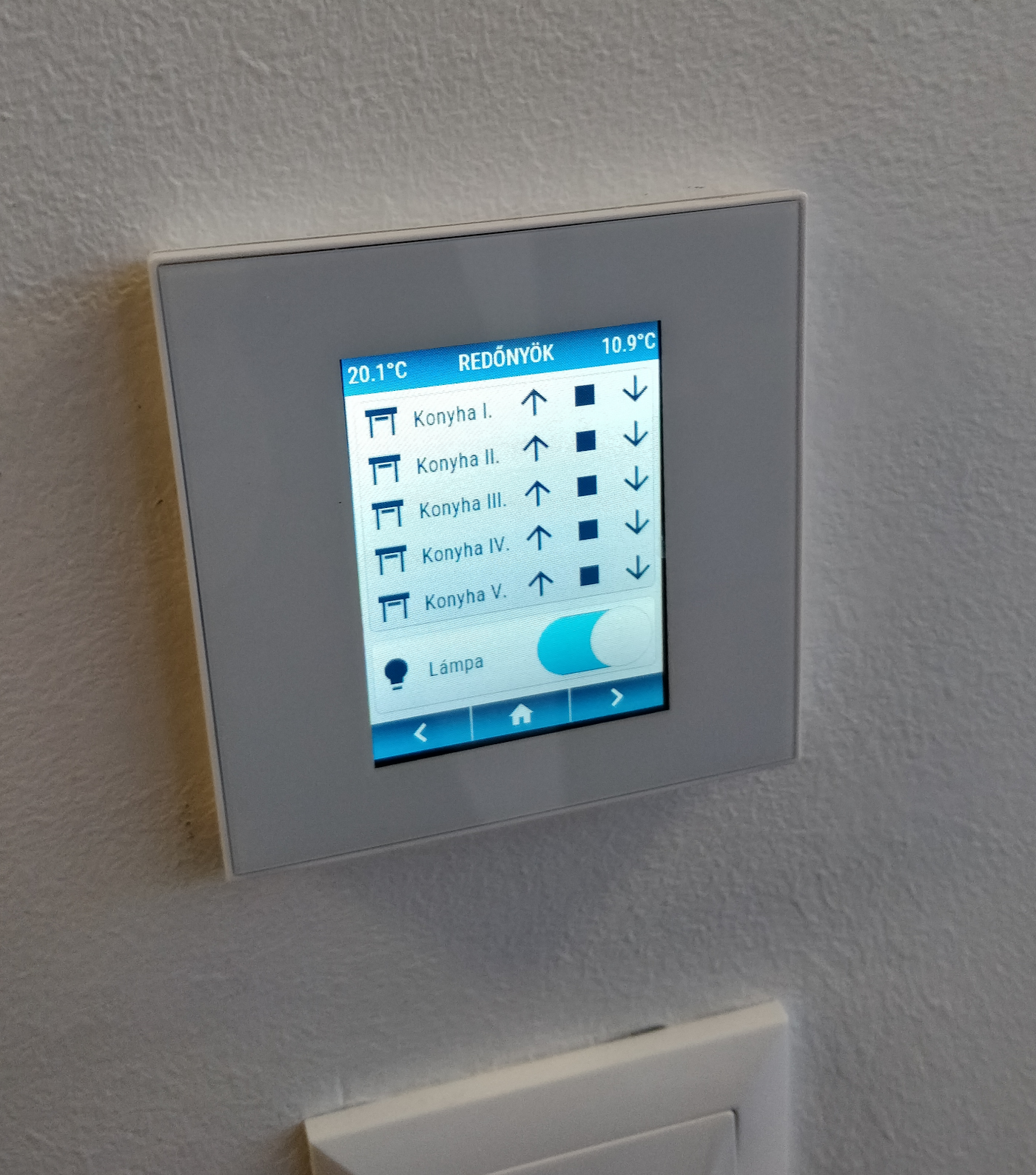
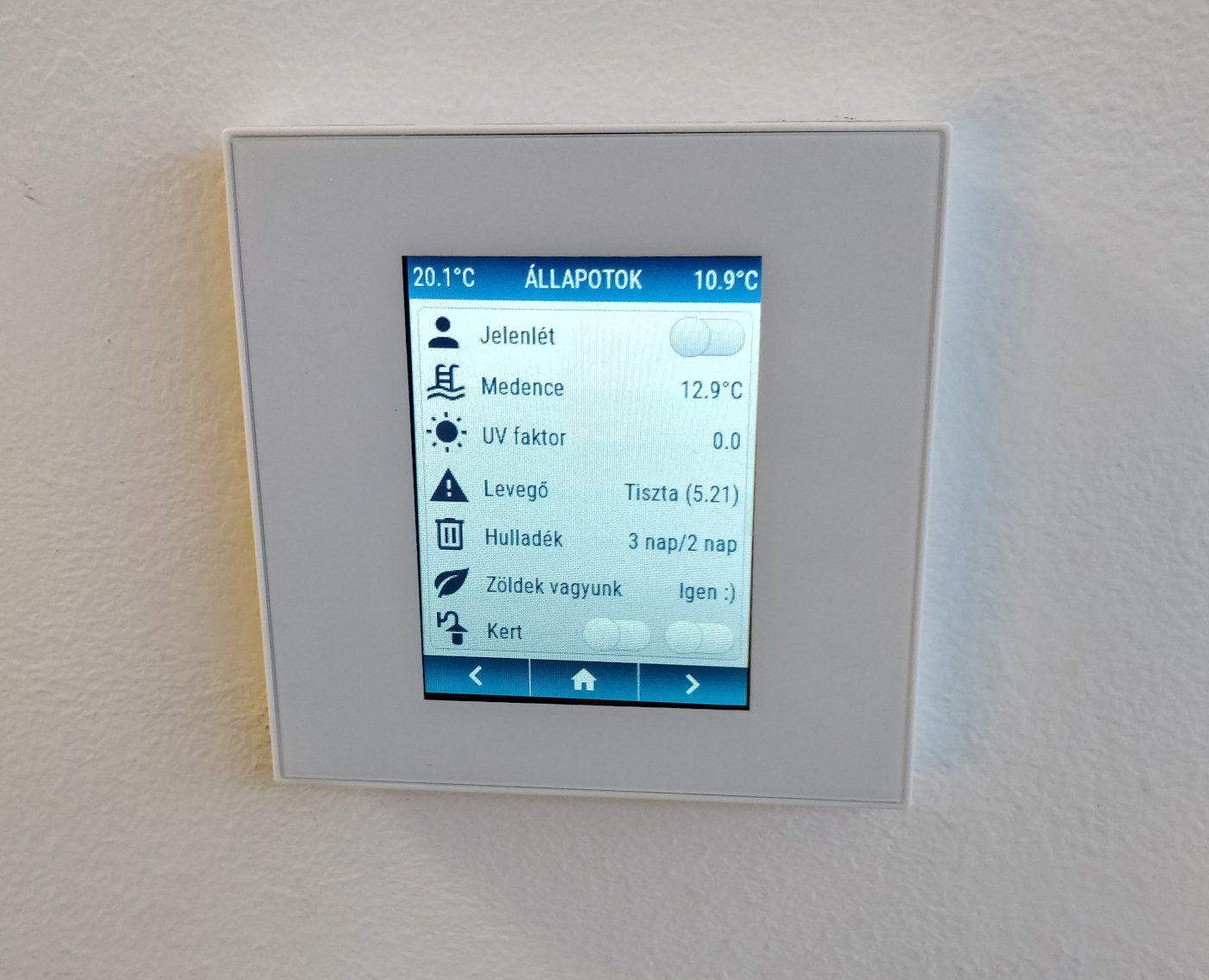
Gallery~
LCD Configuration~
The lcd_config.ini file specifies the different properties of the display, except for the actual pin configuration:
1 2 3 4 5 6 7 8 9 10 11 12 13 14 | |
HASP build_flags~
Specify the LCD Configuration to use and define the GPIOs in the environment build flags:
1 2 3 4 5 6 7 8 9 10 11 12 13 14 15 16 17 18 19 20 21 22 23 24 25 26 27 28 | |