GPIO Settings~
GPIO Overview~
You can attach external devices like buttons, switches, relays, lights or LEDs using the GPIO pins of the ESP. The Devices section of the documentation contains pin descriptions and ways to set them up for specific hardware configurations.
When integrated with Home Assistant, the configured GPIOs will be added automatically during discovery as appropriate entities in the system.

Input Pin~
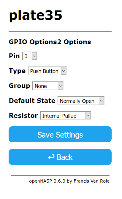
Pin~
Select the GPIO number of the input pin to use.
Note
Pins known to be in use will be hidden from this list of available pins. Check the documentation of your board to see which pins are free to be used as GPIO.
Group~
GPIOs and objects can be grouped together by specifying a groupid. The state of objects in the same group is altered by the value of this input.
This allows for simple action-reaction scenarios without relying on a home automation system:
- Link a switch and relay together
- Link a push button and doorbell together
The state of a digital input can only be on or off and will set all group members to either 100% or 0% of their maximum value.
Note
The grouping of multiple gpios and objects together is intended for simple actions only. More complex actions should be performed by a home automation system, without linking groupids together.
Default state~
The state of the input when it is not being engaged: i.e. the switch, button or sensor is idle (not active):
- Normally Open: The default state interrupts the circuit
- Normally Closed: The default state completes the circuit
Resistor~
To avoid ghost events and RF interference each input should either have a pullup or pulldown resistor.
This ensures the signal in the default state is always HIGH or LOW respectively.
Most input pins have either an internal pullup or pulldown resistor that can be activated by the firmware.
Check the documentation of your MCU whether the pin you want to use provides this functionality.
If an internal pullup or pulldown resistor is not available on that pin you must add an external resistor and connect it either to 3.3V or GND.
- Internal Pullup: The pin is pulled
HIGHinternally by the firmware - Internal Pulldown: The pin is pulled
LOWinternally by the firmware - External Pullup: The pin is pulled
HIGHby an external resistor - External Pulldown: The pin is pulled
LOWby an external resistor
Type~
- Button
A button gpio sends events to topic input# where # is the pin number.
GPIO buttons send out events while they occur. The possible events are:
down: Occurs when a button goes from depressed to pressedup: The button was released within a short time i.e. a short click has occurredlong: A single LONG event is send when the button is still being pressed after the threshold time of 400msrelease: The button is released after being pressing for a LONG threshold time.
The values of objects or gpios with the same groupid will be set to maximum when the button is being pressed and to minimum when the button is released.
- Switch
A switch gpio sends events to input# where # is the groupnumber.
GPIO Switches send out their value when toggled: {"val":"0"} or {"val":"1"}.
The values of objects or gpios in the same group will be set to maximum when the switch is turned on and to minimum when the switch is turned off.
Idle State
The input pins do not affect the idle state of the device. Only interacting with the touchscreen automatically resets the idle state.
If you want a GPIO pin to wakeup the device then you should monitor its mqtt topic and use the idle and backlight commands appropriately.
Output Pin~
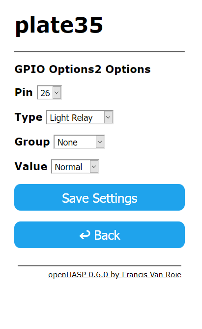
Pin~
Select the GPIO number of the output pin to use.
Note
Pins known to be in use will be hidden from this list of available pins. Check the documentation of your board to see which pins are free to be used as GPIO.
Group~
The applied value is normalized and proportionate to the value of the input object, much like a percentage:
- Binary objects, like a switch, checkbox or toggle button only pass along 0% and 100% values.
- Range objects, like a slider, arc slider, roller or drop-down list pass along a value between 0-65535, depending on their current
min,maxandvalattributes.
Type~
Dimmable Lights:~
- Led
- L8-HD (EU)
- L8-HD (AU)
Set the brightness of the light or LED between 0 and 255 when a value is received on output# where # is the groupnumber.
When a led is controlled by a button or switch in the same group, it will be turned ON or OFF according to the state of the button or switch.
When a led is controlled by a range object (slider, arc slider, roller, drop-down list) in the same group, the brightness will be proportional to the .val value of the object within its range (min-max).
Example
Consider a roller or drop-down list with 4 options: OFF, Low, Medium and High.
The .val values can range from 0 to 3.
These will set the brightness of the led to 0 (0%), 84 (33%), 170 (66%) and 255 (100%) respectively.
For a roller or drop-down list with 5 options, .val ranges between 0 and 4. The brightness of the led increases 25% with each step.
Moodlight:~
- Mood Red
- Mood Green
- Mood Blue
Assigns the pin to an RGB channel of the moodlight. The three RGB channels can be controlled together using the moodlight command.
Relays:~
- Light Relay
- Power Relay
Set the relay ON or OFF when an event is received on output# where # is the groupnumber or from another group intput.
When a relay is grouped with a button or switch in the same group, it will be turned ON or OFF according to the state of the button or switch.
When a relay is controlled by a range object (slider, arc slider, roller, drop-down list) within the same group, the state will be be ON if the val value is larger then its min value.
The various relay types (Light, Power) denote only the device class you want them to be autodetected as in Home Assistant: light vs. switch etc.
Warning
Attaching devices to mains power can be dangerous! Configuring gpios is done on your own responsibility. Be sure to test any system thoroughly using low voltages first. By using the firmware you accept the License.
Use the hasp/
1 2 | |
PWM~
Experimental
Set the duty cycle of the pin between 0 and 4095 when a value is received on output# where # is the groupnumber or from another group intput.
When the PWM gpio is grouped with a button or switch, its duty cycle is either set to full-duty or off according to the state of the button or switch.
When the PWM gpio is grouped with range object (slider, arc slider, roller, drop-down list), the duty cycle is proportional to the .val value of the object within its range (min-max).
Click 'Save Settings' to save your settings to the device. A restart is required to make the settings active. Navigate back to the Main Menu and click Restart to activate the settings.